5G physical layer specifications

The 5G specifications have been published as the 3GPP 38 series. Here we look at the physical layer specifications.
38.211: Physical channels and modulation
The scope is to establish the characteristics of the Layer-1 physical channels, generation of physical layer signals and modulation, and to specify:
- Definition of the uplink and downlink physical channels
- Frame structure and physical resources
- Modulation mapping (BPSK, QPSK, etc.)
- OFDM signal generation
- Scrambling, modulation, and up-conversion
- Layer mapping and precoding
- Physical shared channel in uplink and downlink
- Reference signal in uplink and downlink
- Physical random-access channel
- Primary and secondary synchronization signals
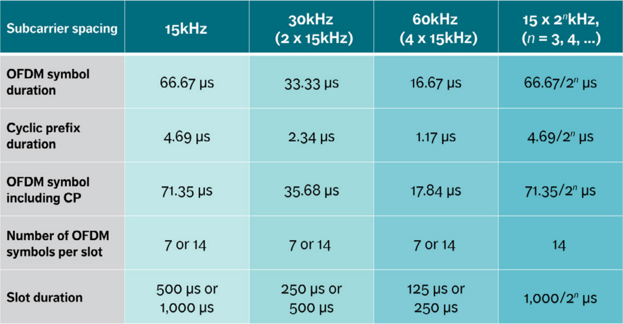
5G transmission numerologies
5G supports OFDM numerologies (μ) that can scale across the sub 6GHz to the mm-waves. The subcarrier scales from 15 KHz to 240 KHz (Δf).

The OFDM symbol duration and the cyclic prefix duration scale based on the numerology.
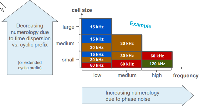
The selection of numerology will depend upon the size of the cell and the frequency band. Large cells have a considerable time dispersion at the receiver. A large cyclic prefix is needed to counter the larger time dispersion. Higher numerologies are preferable for higher frequencies as the wider subcarrier is less susceptible to phase noise.
Frames and subframes
Downlink and uplink transmissions are organized into frames into a 10ms frame as shown below:

Where:


The frame consists of 10 subframes of 1 ms each.

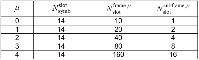
Slots
Just like LTE, a slot is always 14 symbols. The number of slots in a subframe depends on the numerology μ.
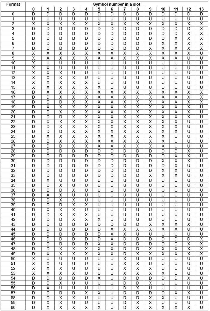
Symbol level TDD
5G slots support symbol level TDD formats. Each symbol can be designated as:
- D: Downlink
- U: Uplink
- X: Flexible
UE assumes that downlink reception can take place only in symbols marked D or X in the following table.
Similarly, the UT can transmit in the uplink only in slots marked U or X.
TS 38.212: Multiplexing and channel coding
The scope is to describe the transport channel and control channel data processing, including multiplexing, channel coding and interleaving, and to specify:
- Channel coding schemes
- Rate matching
- Uplink transport channels and control information
- Downlink transport channels and control information
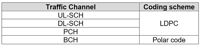
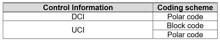
Channel coding
5G NR traffic channels are encoded using the LDPC (Low Density Parity Check) coding. Control channels are encoded with the Polar codes.
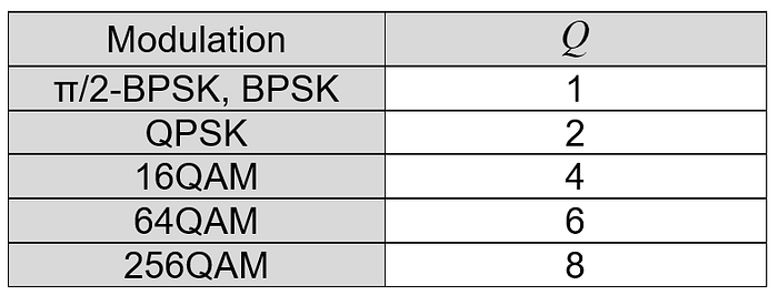
Modulation schemes
5G-AN supports 1 to 8 bits per symbol (Q).
Downlink Control Channel (DCI) formats
A DCI transports downlink and uplink scheduling information, requests for aperiodic CQI reports, or uplink power control commands for one cell and one RNTI.
- DCI format 0_0 is used for the scheduling of PUSCH in one cell.
- DCI format 0_1 is used for the scheduling of PUSCH in one cell.
- DCI format 1_0 is used for the scheduling of PDSCH in one DL cell.
- DCI format 1_1 is used for the scheduling of PDSCH in one cell.
- DCI format 2_0 is used for notifying the slot format.
- DCI format 2_1 is used for notifying the PRB(s) and OFDM symbol(s) where the UE may assume no transmission is intended for the UE.
- DCI format 2_2 is used for the transmission of TPC commands for PUCCH and PUSCH.
- DCI format 2_3 is used for the transmission of a group of TPC commands for SRS transmissions by one or more UEs. Along with a TPC command, an SRS request may also be transmitted.
TS 38.213: Physical layer procedures for control
The scope is to establish the characteristics of the physical layer procedures for control, and to specify:
- Synchronization procedures
- Uplink power control
- Random access procedure
- UE procedure for reporting control information
- UE procedure for receiving control information
Cell search and timing adjustment
The cell search and timing adjustment procedures have been enhanced to work for 15 KHz to 240 KHz subcarrier spacing.
Power control
The power control scheme has also been extended to work for all numerologies. The 2^μ term in the PUSCH power calculation factors in the different numerologies.

TS 38.214: Physical layer procedures for data
The scope is to establish the characteristics of the physical layer procedures for data, and to specify:
- Power control
- Physical downlink shared channel related procedures
- Physical uplink shared channel related procedure
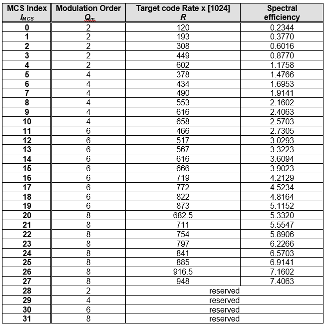
Downlink MCS index table
The downlink MCS index table specifies the modulation, coding, and the overall spectral efficiency of the PDSCH.
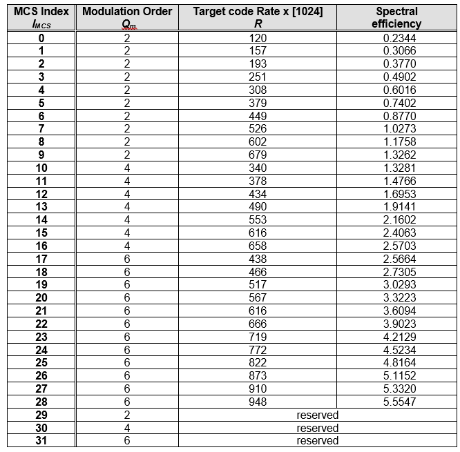
Uplink MCS index table
The uplink MCS index table specifies the modulation, coding, and the overall spectral efficiency of the PUSCH.
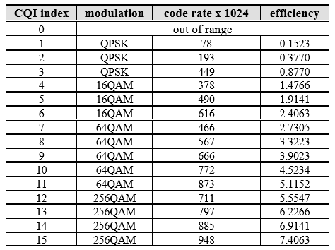
Downlink CQI reporting
The UE reports downlink CQI via a 4-bit field that is carried over the PUCCH or the PUSCH. Two different tables are defined.
- CQI reporting limited to 64-QAM

- CQI reporting extended to 256-QAM
TS 38.215: Physical layer measurements
The scope is to establish the characteristics of the physical layer measurements, and to specify:
- Control of UE/NG-RAN measurements
- Measurement capabilities for NR
5G NR physical layer introduction
The following video provides a good overview of the 5G NR physical layer. The topics covered are:
Waveforms and frame structure
- Scalable numerology
- Numerology multiplexing
- Dynamic TDD
Millimeter waves
- Beam sweeping
- Beam management
- Massive MIMO
Low latency
- Mini slots
- CBG (code block group) retransmission
- Front loaded DMRS (demodulation reference signal)
This blog was brought to you by VisualEther. VisualEther helps you generate call flow diagrams from Wireshark output.

