As discussed in the previous 70310A Precision Frequency Reference post, the pinout and operation of the ovenized oscillator used in this module was a bit of a mystery. Fortunately we were able to locate a copy of the component-level information package (CLIP) for the module, which includes the schematics and connector pinouts.

Here is a view of the oscillator module from a 70310A Option H23 module. Six pins are connected to a grey ribbon cable (red shows pin 1), and the 10 MHz output is connected via an SMA connector.
This particular oscillator is from a different vendor from the one in the first 70310A we disassembled:
Older 70310A — OvenAire-Audio-Carpenter OSC 42–21A
Newer 70310A — McCoy OSC92–13B
Unfortunately, no data sheets for this unit were easily locatable.
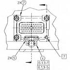
When the grey ribbon cable is traced back to the A2 Power Supply/Processor Assembly, it is connected to J3:

This is a 10 pin connector, with pin 10 removed. Here is the pinout of J3 from the service manual:
Pin 1 — GND
Pin 2 -> Oscillator Heater Power (+20 VDC at 0.5 Amps)
Pin 3 <- Oscillator Oven Temperature
Pin 4 -> Oscillator Power (+20 VDC)
Pin 5 -> GND (Oscillator Power Return)
Pin 6 — EFT (Connected to GND)
Pin 7 — Oven Sense (Shorted to Pin 8 via the ribbon cable)
Pin 8 — GND (Shorted to Pin 7 via the ribbon cable)
Pin 9 — GND (Not connected to ribbon cable)
Pin 10 — No Pin (Not connected to ribbon cable)
Here’s the schematics of how the oscillator is interfaced:

- Heater power is directly connected to DC power.
- OSC power is enabled when Oven/EXT CONT is enabled by the RF Section. This turns off the oscillator when an external reference is provided.
- Oven Sense is pulled to 5V, and indicates when the over module is disconnected (such as in OPT 002).
- Oven Temperature is compared against a reference voltage to determine when the oven has reached a stable temperature. This then is used to indicate if the oven is still cold.
- EFT is not used, and is tied to ground.
This provides sufficient information to use this oscillator in other projects.
A couple of interesting observations is that the 70310 is not disiplining the oscillator based on the external reference, when present. Rather, the oscillator is simply disabled.
This should allow for a straightforward replacement of the module with a rubidium oscillator, and there is room in the module to run a reference in cable from the rear of the module, if required.
Distribution Amplifier
The board at the top in the below picture distribution amplifier “B”, which was not populated in the first 70310A we disassembled. The ribbon cable connecting it provides power, board and input detection and basic self-test.

Additional Module Resources
Component Level Information Packages (CLIPs):