One popular aspect of the HP Modular Measurement System (MMS) was a series of custom and semi-custom RF switching modules designed for specific test, measurement and ATE (Automated Test Equipment) applications.
These products even survived the discontinuation of the MMS product line, as can be seen in this Keysight branded Custom Switch Matrices document on the left.
Details about the MMS offerings are found on page 9:
“Keysight provides custom switch matrices up to 50 GHz in the MMS platform. These are the Keysight 70612X series matrices. In addition to these custom solutions, Keysight offers a family of standard MMS switch matrix modules. These are the 70612A/C and 70613A/C. For more information on these matrices, refer to the MMS catalog, publication number 5965–2818.”
Publication 5965–2818 was unavailable for a long time, but recently resurfaced. It provides a comprehensive catalogue of MMS products from HP and other vendors, and is required reading for everyone interested in the MMS product line, and can be downloaded at:
http://www.hp70000.com/manuals/5965-2818_MMS_Catalog.pdf
70612C K63 Overview
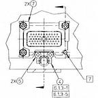
The 70612C K63 RF Input Drawer is an example of a later build of one of these switching products. The K63 option is a revision of the earlier K08 option, and is Agilent branded. It is designed to connect together many different pieces of test equipment, including:
- Noise Source
- Spectrum Analyzer
- Power Sensor
- Network Analyzer
- Signal Sources
- Filter Assemblies
- Unit under test
These pieces of test equipment are connected to the front panel using 3.5mm precision connectors, with all switch paths supporting signal frequencies up to 26.5 GHz.

As can be seen, this is a complex switching system, with many inputs and outputs. In fact, it has 46 unique signal paths!
Inside the 70612C K63

As seen from the top, the major components of the 70612C K63 are:
At bottom — MMS Switch Controller board, with two Switch Driver boards immediately above.
Left side — 3PT Microwave Switches
At top middle — 1P6T Microwave Switches
At top right — Two Attenuators
A closeup of the Switch Driver boards shows that these are late model and Agilent branded, using surface mount components.

Likewise, the attenuators are also quite modern:

The switching logic is quite complex, and is most easily understood via a diagram:

The functional signal flows are as follows:
- RF Input 1 is attenuated, then switched between UUT1, UUT2, Filter Output 1, the Monitor Port, and either the Spectrum Analyzer or the Power Sensor.
- RF Input 2 is attenuated, then switched between UUT3, UUT4, Filter Ouput 2, the Monitor Port, and either the Spectrum Analyzer or the Power Sensor.
- RF Input 3 is switched between either the Spectrum Analyzer or the Power Sensor.
- The IM Input, Noise Source, or Analyzer Input can be switched between the IM Monitor Port, UUT 1–4, and either the Spectrum Analyzer or the Power Sensor.
- Finally, one of UUT1 through 4 can be set up as an input (such as when measuring reflection), and routed back through to either the Spectrum Analyzer or the Power Sensor.
This is quite flexible, and allows for many useful measurement scenarios. For example, two RF signals can be generated using 70340A modules, each connected to the RF Input 1 and RF Input 2. UUT1 and UUT4 can be connected to a mixer, with the output of the mixer connected RF Input 3. With a noise source connected, the response of the mixer with different input frequencies and amplitudes can be measured, along with the results of noise inputs on each of the mixer inputs.
Module Resources
Hardware Reference Manual: