Why I build an irregular bike — Part #2
With the frame in an nearly finished state by the end of May, I spend an awful lot of time thinking how it all would work in the end, because this is kind of where the guidance ended from the open source building plans from N55.
They delivered specs in the document on which set of wheel sizes, hinted material and some structural requirements. I know the steering system had to be based on Ackerman, but it was hard to figure out by looking at the few technical drawings how it was supposed to work. Next to that, shifters, gears, mounting the bottom bracket and brakes… I was quickly lost in complexity.
It was not before a long time I would pick this up again… and started carefully laying out parts in a document I made. Lining up required sizes, standards that needed to match in order to work together. A would fit on B, B would fit on C, to be continued to Z, and Z needed to fit on A again. A double and triple check on everything, I started ordering parts… starting off with the bottom bracket, which has a little separate story in Part #3.

From the bottom bracket, I slowly build the bike. My rear hub came from Japan, a classic 3 speed internally geared hub, with a neat shifter, supplied by the same party. It arrived in the mail after a slow, long month wait. This is often how it went down, by waiting to buy part by part, I spend most of my time in the late summer waiting for things to arrive, with an even bigger challenge on the horizon I did not see yet…

Meanwhile, I was also coming up with my own ideas how I could utilize the design of the bike to make the non-existing light setup in the design a working thing. I love how VanMoof worked their lights into the frame, and I wanted that too.
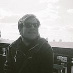
So I designed a little electrical circuit, driven by a set of LiPo batteries or 9V block, included in this design were the specs of the LED and mounting holes. Those were custom 3D printed on 3D Hubs. I can recommend their platform for anyone needing a specific piece that you can mock up in 3D quickly, no need for complex manifacturing. That’s why there are red and white wires running out of the frame on the photo above.

The seating had to have some stickers ;). In this photo you see that I was able to mount a bottom bracket & rear wheel successfully. What you also can see that I’ve got disk brakes on the front two wheels. That’s been a design decision that I regret for some part, but it looks badass, until now, where I had to figure out a good way of controlling and mounting the brakes.
The rear wheel was a good challenge, as I spoked it myself. Definitely learned a lesson there, I was capable of doing it, but I recommend having a specialist do it, even if it’s costly. It might look easy on Youtube, but this is an art, don’t forget.
The seating looks temporary, but it’s actually permanent. It’s a solid piece of polycarbonate that is very flexible, that actually bends nice to your body when you sit in the seat itself.
In part #3 I’ll cover what my biggest bottlenecks were finishing this piece. Including a first test ride and the totally unexpected accident that occurred.