Centralized optimization model for multi-microgrids [Part-1]
When several distributed energy resources and loads are combined to function as a single controllable entity, it is referred to as a “Microgrid”. Multiple microgrids can be interconnected with each other to lower the collaborative system operation cost. Such a multi-microgrid system is given in the figure below:

The above system consists of two interconnected microgrids. A single microgrid has a diesel generator (DG), a renewable energy source (wind turbine), and a battery to serve its local electricity demand. Each microgrid is connected to the utility grid to buy and sell the electricity. The central management system (CMS) determines the optimal operational schedule of each microgrid over the day horizon. The CMS is designated to minimize the collaborative system operation cost of the interconnected microgrids.
Mathematical Modelling:
Our problem is an optimization problem given the objective is to minimize the collaborative operation cost of interconnected microgrids. We will formulate the mathematical model of our problem. For reference, the figure below describes the symbols, indices, constants, and variables used during the modeling of our system.

The objective function is to minimize the operation cost of the system. It consists of the cost of generating power from the DG and the cost of power exchange (buy/sell) from the utility grid. Mathematically, the objective function can be stated as:

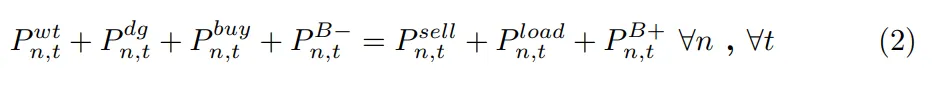
The microgrids must meet the energy balance constraint at each time interval. This constraint is expressed by the bellow equation.
The set of constraints in the below figure are the limiting constraints of each component of the microgrid. Eq. (3) and Eq. (4) relate to the maximum charging and discharging limit of the battery, whereas Eq. (5) is the DG operating limits constraint. Eq. (6) refers to the state of charge (SOC) level of the battery.

The following figure describes the battery operating constraints. Eq. (7 ) shows that the battery can only be discharged by the amount of power currently stored inside the battery. Similarly, Eq. (8) states that the battery can only be charged by the amount that is the remaining battery capacity. The Eq. (9) gives the SOC level of the battery at a given time. Charging increases, while discharging decreases the SOC level.

In this blog, we saw how we can develop the centralized optimization model of a multi-microgrid system. In the second part of the blog, we will look into the CPLEX implementation of this problem and the obtained results.
If you have any feedback let me know in the comments below!