A Deeper Insight Into Face Authorization System
Written by Piotr Smuda and Piotr Tempczyk

About the project
The project goal was to build an automatic authorization system based only on people’s faces and documents. Such a system can be used at the conferences, in medical centers or airports and has a big potential to replace manual identity verification.
We encourage you to read more about the project as a whole and its flow in the AI-Based Real-Time Face Authorization System blog post. In this article, we will focus only on some of the most interesting technical details of the final solution.
This entire project was done as part of research conducted by the Daftcode AI Team. The code of our solution can be found in this repository.
Face detection and recognition
We used David Sandberg’s implementation of a FaceNet to confirm a match between document photo and frames of the video live stream from a 3D camera (the video was in 2D, depth map was only used for the anti-fraud tool). David’s implementation uses 512 neurons for the face embedding, as opposed to 128 neurons in original paper implementation.
Despite the fact that FaceNet has been trained to be insensitive to change of illumination, the imitation of a photographic studio lighting for face recording helped algorithm to achieve better results. Another thing that helped was comparing faces in grayscale, especially for IDs. At the end sometimes it was better to compare grayscale document photo and video in color anyway, but in the final solution, we used maximum from similarity measures calculated on grayscale and color video.

There is a problem with David’s implementation of FaceNet. The algorithm used for face localization doesn’t upscale the face when its size is smaller than 160x160 pixels (size of the input for the neural network). The bigger part of size 160 x 160 around the face is taken and we end up with a very small and fuzzy face, which is hard to recognize. Effect of this is presented in Figure 1.

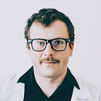
When the face is bigger than this size it is downscaled to match 160x160 region and it is much clearer and with more details, as can be seen in
Figure 2. This problem appears especially with low-resolution cameras or when people stand far away from the camera.
Document type classification problem
For document type detection we have applied a modification of the k-means algorithm with known cluster means. We have selected the upper left corner of each document for its representation. Visual representations of cluster means are presented below:


For calculating the cluster means we used several data augmentation techniques: the images were blurred and randomly shifted vertically and horizontally and every scanned document was used more than once. The mean was calculated on about 10 real documents for each type of a document.
The processed document image was also blurred and L1 metric was calculated between the pixels of the image and a cluster mean. Then the matrix was binarized by checking for each pixel if a certain threshold distance was exceeded. Finally, the mean of this binary matrix was calculated as the distance between the image and the cluster mean.
If the distance to the nearest cluster was in the tolerance region then the document type was selected. Otherwise, the document was recognized as ‘unknown document’. For the implementation details, we recommend checking the DocumentTypeDetector class implementation.
Cutting out the personal data
It might seem that personal data is occupying the same space at each document of selected document type, but it is not true. There is some random shift between the field name and the field content (for example on ID Card between “SURNAME” and “TEMPCZYK”) and between field name and the eagle emblem on ID (or any other element from the background graphics of a document), so it is impossible to choose one rectangle for each field which will be good for all documents of a selected type. And when some letters from field name will be introduced in the rectangle, the OCR will fail to do its job and to properly recognize the text in the field. So we had to write an algorithm to automatically detect where are the necessary fields on each document.
In the beginning, the function cuts the area inside where the upper left corner with the necessary fields is supposed to be.

Then it tries to detect where the letters are. Because the text is darker than any element of the background, the algorithm takes the minimum color value on each pixel across the RGB channels.

This matrix of minima is then re-scaled to have values between 0 and 255 and binarized by checking if each matrix value is below a certain threshold. This operation produces the binary text map with the information for each pixel whether it is a part of a letter or not.

The sum across each axis of the matrix is calculated to make it easy to check where the first character begins. Effect of this operations is presented in Figure 11 and 12.


In Figure 12 we can see the first bigger hill for the 1 and 2, and the second smaller hill for the dots after them. In this representation, the function can easily find where the text starts and localize the upper left corner for trimming. The final effect for old driving license looks like this:

For each document, this procedure looks similar except the student’s card, where the first and last name is placed on a big area without any other fields so it can be easily cut out with fixed coordinates.
Personal data OCR
We used the Polish version of Tesseract OCR 4.0 for the name recognition. Tesseract is normally used to recognize letters written on plain paper and it achieves the best accuracy for such data. The background of scanned documents often contains letters or certain character-like patterns. The letters are also not so much outstanding from the background.
When we feed raw data from Figure 13. to the Tesseract it generates names with additional letters from the background (especially with old ID, where letters RP appear in the background of the name field). The algorithm behaves also not so well with data looking unnaturally (with very high contrast), so making a binary mask of text/not text doesn’t work so well.
To remedy this we did the following. We took a max of three color values to brighten the background compared to letters and made it monochrome. This operation also helps to make pink background letters less distinct compared to Figure 13. The picture after this transformation is presented in Figure 14.

After that, we blur the image…

…and make a binary mask of text/not text taking values above a certain threshold and then blur it again.

At the end, we mix blurred image from Figure 15. with the blurred mask from Figure 16. in proportion 3/4 and 1/4 which makes the letters stand out from the background while preserving the natural look of the whole image.

We pass this mixed image to the Tesseract image_to_string() function.
Anti-fraud tools
Analysis of depth surface
Our authorization system contains simple anti-fraud tool based on a depth camera. The main idea of it is to treat detected faces like some kind of surface and find holes corresponding to the eye sockets.
The proposed algorithm is inspired by gradient descent and works in a similar way. At first, for each person’s face image, the middle area of it is selected (50% of width and 80% of height). Then, we try to detect the position of the nose (x, y). Because the nose in a typical situation should be somewhere in the middle of an image and be the nearest points to the camera, we take a median of detected nearest points on depth image.
Next part of the algorithm is related to finding eye sockets. At the beginning, the 6 starting points are nominated, from which we start searching for the holes (coordinates in pixels): (x, y), (x-10, y), (x-20, y-20), (x, y-10), (x+20, y-20), (x+10, y). Such a selection of points would increase robustness and focus search in the higher parts of a depth map of a face. Then, for each starting point the following sequence is repeated 5 times:
- For actual point (x, y), area [x-2, x+2] x [y-2, y+2] is selected.
- The farthest points (from the camera) are chosen.
- One point from them is randomly selected and became the actual point.
- Points 1.-3. are repeated until the farthest point is reached (there is no movement between steps).

Next, it is checked how many of the final points are in the center of the middle area (80% of middle’s width and 50% of middle’s height). If more than 50% of the points were in the area, then the image was accepted as “real face”. Finally, we assumed that wasn’t fraud if more than 50% of frames in a person’s recording contained “real faces”.
Facial key points
We also tried an anti-fraud solution based on a liveliness of face. For this, we used a pretrained face landmark detection model from dlib library. Using it, we could check whether the recorded person is blinking during recording and does it look natural.
To do this, on each eye we designate 4 landmarks, 2 for each eyelid to investigate the change in time of distance between corresponding points from the upper and lower eyelid. For each captured frame we compute Euclidean distance and store it in the memory buffer with length of 10. After every 7 subsequent frames we inspect whether all distances of 2 landmarks pairs (normalized with their means) are in the range of [-(mean + 1.2), mean + 1.2]. If it was true then we treated it as a fraud.

Unfortunately, it was GPU consuming process and wasn’t effective enough, so it wasn’t included in the final solution.
Conclusion
To sum up, the project was full of challenges, which sometimes required dedicating many hours and a thorough rethink of different approaches. Furthermore, the presented solution can be transferred to other documents, what would make it possible to create a similar system for another countries.
The code of our solution can be found on Daftcode’s GitHub.

References
- F. Schroff, D. Kalenichenko, J. Philbin, FaceNet: A Unified Embedding for Face Recognition and Clustering, https://arxiv.org/pdf/1503.03832.pdf
- K. Zhang, Z. Zhang, Z. Li, Y. Qiao, Joint Face Detection and Alignment using Multi-task Cascaded Convolutional Networks, https://arxiv.org/pdf/1604.02878.pdf
- R. Smith, An overview of the Tesseract OCR engine. Document Analysis and Recognition, 2007. ICDAR 2007. Ninth International Conference on. Vol. 2. IEEE, 2007.
If you enjoyed this post, please hit the clap button below and follow our publication for more interesting articles about ML & AI.