Android SmileyRating (How I solved it?)

Here I am going to write about how I created the SmileyRating library and what are the problems I have faced. Before that, I want to thank @Yousef Kama for sharing his work experience based on BillLabus’s design.
SVG -> VectorDrawables -> Canvas
I started learning SVG to achieve this animation since we can avoid using images and simply draw paths to create simple shapes. But in android, I can’t use SVG natively without using a third party library. Instead, Android is having another image type called VectorDrawable. I started exploring it and bumped into this article(link) which helped me to understand path morphing animation. But that was not enough. Even if I could create different smileys and morph between them, I can’t control the animation. I can only start and stop it. I can’t pause the animation at a particular frame. So I decided to write it using Java(Android) native canvas API.
Mouth
The first step is to create a mouth. So according to the link, I shared you about the path morphing animation, “If you want to morph one object into another (eg: line to curve) it should have the same number of commands with the same number of parameters and same command sequence order.
eg: line to curve

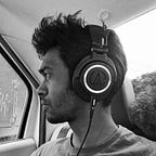
In this example, I just created a bezier curve using Android canvas. Bezier curve has two actual points and two control points. Two circles drawn in red color are control points and black circles are actual points. Here when I move the control points down, the curve becomes a line and when I move the control points up, the curve is formed again. Now if you see this upside down, you will get how I achieved the mouth animation.
Joining curves
It may seem simple to draw a bezier curve. But the problem was, I had to keep the edges curved to draw the mouth. Using one curve, that’s not possible, using two curves it is hard to maintain a curvy edge, So I came up with an idea of joining four curves together. That’s when I found out a great video about bezier curve joining(link). If you are combining bezier curves, you have to make sure that the control points shares the same actual point(eg: Curve one’s end point and Curve two’s start point become same when you combine them) should be opposite to each other with same distance away from the actual point. For example, if one control point is at 90° and 30 pixels away from actual point, then the opposite control point must have to be at 270° and 30 pixels away from the actual point.

The above image is the example of two curves joined together. Here the first curve one’s EndControl point and curve two’s StartControl point is opposite to each other and took the joint(Two curves junction point) as the center point. As long as you keep these two control points opposite to each other and the same distance away from the junction point, the curve will be continuous. Like this, I joined four curves together to form the mouth of the smiley.
Smiley Model
The next problem I faced was managing all the coordinates required to draw the mouth(Smileys: TERRIBLE, BAD, OKAY, GOOD and GREAT). There are totally 4 curves(left, top, right and bottom) with 12 coordinates. So I created a model which reduced the complexity of creating the smiley. The basic idea is that in every smiley, the left side always looks like the right side but with small change. There are three creation states in that model.
- MIRROR
- MIRROR_PARTIAL_INVERSE
- MIRROR_INVERSE
Mirror
In this type, I just have to provide the smiley’s center point(x, y) and left side curve’s coordinates(start, end, startControl and endControl points).

In this image, the white point represents the center of the mouth area, black circles represents control points, blue circles represents actual points and green circles are the opposite points created for the bezier curve to be formed and joined. Blue colored dashed lines represent the left side curve. Now I have to tell my model to create the right side curve by mirroring the coordinates we have now to get the right side curve and its opposite coordinate points.

If you look closely, we now got all the coordinates to create the top and bottom curves. Yes, the green dots from the past two pictures are the control points and blue dots are the actual points of the top and bottom curves. Let’s form the bottom curve and see how it looks.

Same way the top curve is also formed using the coordinates formed by this model. By adjusting the left side curve I can create different forms of smileys.
example: GOOD Smiley

MIRROR_PARTIAL_INVERSE
This model is used in only one Smiley(OKAY). This smiley is nearly same as MIRROR, but with one more functionality. Here also the right side is automatically formed by mirroring the left side curve, But the right side will also be entirely flipped vertically.

You can clearly see that the left side is mirrored and inverted on the right side. Top and bottom curve is flattened since the left and right control points are formed parallel to each other.
MIRROR_INVERSE
This is also similar to both MIRROR and MIRROR_PARTIAL_INVERSE. The left curve will be mirrored and this time the entire mouth of the smiley will be flipped vertically. So basically if you have coordinate for the left curve of GOOD smiley, then you can pass it here to for BAD smiley.

You can see that this is exactly like GOOD smiley flipped vertically.
Animate Smileys
Animating is the simplest part here, all you have to do is evaluate the value between the coordinates of the smileys by the fraction of 0 to 1.
eg:
This example will calculate the leftCurvePointX value of the calculated smiley to be drawn. By combining all smileys you will get the morphing animation like this

Eyes
Eyes are created using arcs because eyes in smileys also should show emotions. So when you are drawing paths using SVG or in Canvas, if you close the path after drawing an arc, it will try to close the arc by drawing a line from startPoint to the endPoint of the arc. In this SmileyRating there are three eye reactions only,

In the above image, I had shown all three reactions of the left eye. The right eye is, as usual, the mirror of the left image. In this picture, the first two eyes look like a sliced circle, but it is actually a half drawn arc which is closed. Not let’s animate this and see how it looks.

Those two dashed lines show the start and sweep angle of the arc. You just need to change start and sweep angles of the arc and rotate the arc to create this animation.
The link to the library is provided below: