This post talks about basics of electric motors for robotic applications. It addresses to everyone who wants to know a little bit about motors. It’s not precise stuff, but future posts will dig deeper into the details of motorization and control in robotics.
What are motors? Which motors can be used for robotic applications? While these questions may appear simple and complex at the same time, let me first tell you what I will not talk about in this post:
- Car engines
- Helicopter and plane engines
- Rocket engines
- Windmill and watermills
- All kinds of non-electric motors
(I know what you think: yet another post that won’t talk about rocket engines, where are we all going, what even is this world, and so on. I know and I’m sorry.) Later on, there are also some kinds of electric motors about which I will briefly talk to acknowledge their existence, but then nothing more.
What I will talk about in this post are the electric motors used in robotics.
Note: The word robotics embraces so many concepts, and the vastness of the definitions and interpretations is so close from infinite that I won’t even try to define it here and now.
Let’s just agree that a robot has a “brain” (computer), some “senses” (sensors) to capture what happens around it, and “muscles” (actuators) to provide motion and interaction with the world.
Now, WHY am I talking you about motors? I’m going to answer to that with three questions (and three answers), assuming my goal is to make robots.
- WHAT DO WE WANT? We want to make robots that move. We want motion. A nice example could be that you wish to design a robotic arm that can lift a banana for you (here is finally what the title was all about).
- WHY DO WE WANT IT? Well, a robot that doesn’t move is not really a robot, is it? More like a rock or a pot of flowers. But again, definitions of robotics vary widely.
- HOW DO WE DO IT? We do it with electric motors. Because today (i.e end of year 2017), electric motorization is the most accessible technology to create motion. Not the only one, of course, but the cheapest, most available, and easiest to use.
We can agree on one hand that robotic devices are better small, well integrated and not too greedy on power consumption. On the other hand, a robot is nice if it can move smoothly, wave its arms or lift things. And be autonomous. (So many nice features could be added to this list, like massage your neck, or make you a sandwich, but let’s keep simple and carry on with the banana.)
This naturally leads us toward small and efficient electric motors, the types than can easily be bought, integrated and controled.
So now that we have a subject (electric motors for robotic applications), let’s come back to the initial question:
What are motors?
An electric motor is a device that transforms electrical energy (electricity with voltage and current) to mechanical energy (linear or — mostly — rotational motion).
The electrical energy is the input of the motor, and the mechanical energy is the output. So for now, if you stop reading after this sentence (but please don’t), a motor is a magic box which is able to make motion from electricity.

This magic, most of the time, is also called electromagnetism. We will talk about that later.
Note: Technically, if you take the same magic box and apply rotational motion to the output (which hence becomes input), you will obtain electrical energy coming from the former-input-now-output side. The result is called a generator, and we will not talk about them more than this note.
There are several categories and subcategories of magic b… hum, of electric motors.
I chose to present them this way. Here is a list of motors’ categories:
- AC Synchronous motors
- AC Asynchronous motors
- DC motors
- Other motors (Stepper, etc.)
But before digging into these, we need some basis.
How electric motors work?
Expect for the some motors of the last category, all the previous in the list use electromagnetism to transform electricity into motion. By running current into a wire coiled around a bar of iron, for example (which is called an electro-magnet), a magnetic field is created and can attract or repulse either magnets, either ferrous materials, either other electro-magnets.
So, basically, here is the recipe:
- Take some coils and place them into a circle (they must not be able to move).
- Take a magnet, and put it in the middle of the circle. The magnet should be able to rotate while staying at the center.
- Put current into the coils, one after another, and watch the central magnet rotate, one of its poles attracted to the powered coil.
Congrats, you just made an electric motor.
Now, be advised that the configurations may vary: coils can be in the center (sometimes around iron, sometimes not), magnets can form the circle, sometimes there can be no magnets at all, and so on. Each configuration is a type of motor from the category list above.
Regarding the vocabulary, these are the main words you will need in order to continue:
- Stator: the part of the motor that won’t move (e.g. the coils of the previous recipe)
- Rotor: the part that will have a rotational motion (e.g. the central magnet of the recipe)
- Coils: Sometimes I may say windings, sometimes coils. A coil is a wire that has a very thin insulating sleeve and is properly wrapped many times around itself or an armature (see below).
- Brushes: They exist only if the rotor has coils. Brushes are a pair of small still parts that make electric contact between coils’ rotor (through commutator), and power supply by friction, allowing the rotor to… rotate.
- Commutators: They exist only if the rotor has coils. It’s the conductive parts on the rotor which comes alternatively in contact with the brushes. Each pair of commutators is wired to a pair of coils on the rotor.
- Armature: ferrous material, sometimes laminated to avoid some vicious electromagnetic tricks, around which is wrapped the winding, or coil.
- Housing: The part around the motor, which protects the inside from all kind of external annoyance (dust, water, poor music, etc.)
- Torque: The rotational force that a motor can provide at output.
- Speed: This one is easy; the rotational speed at the output of the motor.
Note: Both torque and speed are very important data to know on a motor, because they define how much weight a robotic arm can lift (for example), and at which speed it can do that. Some bananas can be heavy, be careful.
Along with them, other concepts like rated voltage, torque constant or no-load current are critical when choosing a motor, but these can be talked about on another more precise post.

Some of these words will help us understand the next part of this post:
Digging into types of motors
From the previous list of motors’ categories, let’s eliminate the first two. Synchronous and asynchronous motors are AC-powered, which stands for Alternative Current. AC mainly comes “raw” from your wall plug, and we can represent it as endless waves of current (sinusoidal curves). It’s not fit for robotics, mainly because it’s way too much power.
Synchronous and asynchronous motors are in general too big for being used in robots, even human-sized ones. (Many DC motors are over-sized too.)

This lets us with a shorten list and many troublesome explanations avoided:
- DC motors
- Other motors (Stepper, etc.)
For each category and subcategory, I will basically explain how motors are made and how they work, then talk about some of their pros and cons, and where we can find them.
Motors Category 1: DC motors
DC means Direct Current. It’s a flat curve of current (different from the AC’s waves), and it is used in batteries, or at the output of most power supplies you use for various devices in your home.
We can divide this category in two parts: Brushed DC motors and Brushless DC motors.
- Brushed DC motors
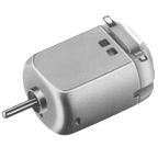
A brushed DC motor is composed of a coiled rotor, and most of the time permanent magnets as stator. As the rotor has winding, it must be power-supplied in order to generate a magnetic field. So we find also brushes and commutators to allow current into the winding.
A small recipe to explain how it basically works:
- Apply power from a battery to the motor’s terminals. The electricity is flowing through the brushes to a first pair of commutators, and then to a first pair of coils.
- The armature around this pair of coils becomes an electro-magnet and has now two poles.
- The north pole on the rotor is attracted to the south pole of one of the stator’s permanent magnets; the south pole on the rotor is attracted to the north pole of the opposite permanent magnet, on the stator. This makes the rotor turn to adapt its position.
- As the rotor turned, the commutators changed position and a new pair of coils is supplied in power, through the brushes and commutators.
- The rotor must turn again to adapt its new position of attraction, and so on.

There is a subcategory of brushed DC motors called coreless motor, which rotor is composed only of a winding without armature, i.e. with no iron core, i.e. coreless. The magnets are situated in the center of the motor, instead of the internal side of the housing like on regular brushed DC motors. This is a common technology in very small brushed DC motors, and offers these pros: high accelerations and high dynamism (because of lower inertia of the rotor), fewer electrical noises, and higher efficiency.
The brushed DC motor is the most common motor in robotics, and the most largely used because of its easiness to produce, and hence its ridiculous price on the market. These are clearly pros, as is their easiness and many ways to control.
Note: We will be coming back another day to explain the different way of controlling a brushed DC motor.
These motors have cons: First of all, the quality is associated to the cost (the cheaper, the worst quality). That means sometimes poor materials, weak assemblies and overheating motors. The brushes, whatever the quality, are a weak part of the motor because they are always in friction with collector. With time, and depending on the use of the motor, the brushes wear and create dust; the connection is thus not always made with the collectors, which results in a significant loss of speed and torque.
At the end, all these cons strongly impact on the motor’s life.
Several famous non-fictional robots have brushed DC motors inside their hardware. Probably some fictional robots have some as well.
Nao, Pepper, Roomba or Asimo: they all have some brushed DC motors inside (and of some other types too).
- Brushless DC motors
As the name makes it explicit, this subcategory of DC motors doesn’t have brushes and collectors to make the electrical connection between power supply and rotor.
The brushless DC motor (BLDC) works on the same principle than the brushed DC motor, electromagnetism. However, the rotor, which can’t be powered, is made of permanent magnets.
The coils of the stator are either disposed around — outside — the rotor (in-runner motors), or in the center — inside — of the rotor (out-runner motors, with the housing being part of the rotor). These coils are arranged by pair located on each side, in order to give them a north pole and a south pole when they are powered. The number of coils is always a multiple of 3, because they are always 3 phases (that’s why 3 wires are coming out on a BLDC).
At this moment I’m sure a picture may be both appreciated and welcomed:

The recipe:
- Power the coils one after the other (you will need a special control board for that).
- A rotating magnetic field is created, making the rotor’s magnet turns to “catch” the changing poles:

That type of motors can be controlled in several ways. In some cases, if needed, the position of the rotor can be extracted, with different solutions. You will find more details in a future post.
Regarding pros and cons, the first pro is clear: no brushes means no contact, no friction, so no wear; that implies best reliability and best efficiency (friction means loss of energy as heat).
The in-runners BLDC will provide more speed than torque, because of their rotor’s inertia. On the contrary, out-runners BLDC will have more torque and less speed. Depending on the desired function this may be a pro or a cons.
An important cons is the price, more expensive than their cousins brushed motors. It’s explained by many factors (winding construction, magnets, some electronic parts, etc.).
Another cons is that BLDC are most of the time trickier to control, and need an electronic control board.
Also, their possible high speed, as for brushed motors, may imply the use of a reducer device at the output of the motors to lower the speed and increase the torque. This always means loss of efficiency but it is very often used.

Note: Reduction is a crucial part in the whole motorization choice process. To stay in the basics, keep in mind that, a reducer — which is composed of gears assembled together — is meant to reduce the speed and, let alone efficiency, to multiply torque of the motor it is coupled to.
Many famous robots have brushless DC motors as well as brushed motors. However, being more expensive and more complicated to control than brushed motors, “cheap” robots and toy robots may not provide any BLDC inside.
Before switching to the next category
I would like to open a side yet important category here, about the servomotors.
This kind of motor is actually more than a motor, it’s a “box” (again) that includes a DC motor (either brushed or brushless), a reduction at the motor’s output axis, a sensor to know the position of the output, and an electronic board for the control.


This actuator is widely used in robotics, because it provides control of angular position of the output, whatever torque must be applied (in the limit of the specifications). It works in closed-loop, the sensor giving a feedback of the position and the electronic board correcting it almost in the same time.
For example, imagine this application on your one-armed-banana-lifting robot: you can choose a precise angle for the arm to be reached, while lifting the yellow fruit. If the banana happens to be eaten at the same time, the weight will change but the arm will stay at the same position, thanks to the closed-loop and the constant correction of position.
Pros are the well integrated functions fitting in a small box, making it very easy to assemble into a larger robotic part; also the control exists already and does not imply to design a new one, which saves both time and money.
Cons are that some of them won’t fit for the application you chose. Also, many servomotors have bad quality and poor control.
Any DC motor could be made a servomotor at the condition you add the sensor, reduction and control functions. Now you know that it already exists as a whole. Neat.
The famous robot walker Asimo is made, as I said earlier, of DC motors. It was partly the truth, because some of its actuators are in fact servomotors made of BLDC motors.
The three robots Poppy, Ergo Jr., and Reachy, highly linked to the French company Pollen Robotics, are made of servomotors.
Actually, servomotors are more often used for personal robotic projects. Why is that? Because a servomotor is cheap compared to all the functions it provides (motorization, reduction, sensor, closed-loop control). You may not happen to have a lot of money to carry on personal projects, and find yourself facing this choice:
- find a DC motor, design a reduction, and dig yourself deep into the jungle of motor control, which can take weeks, if not months; or
- buy yourself a servomotor in order to be able to lift that banana of yours on the same day you buy them (not quite sure you’d find both the servomotor and the banana in the same shop, though).
The choice is kind of obvious.
Additionally, famous and cheap tools (like electronic boards Arduino, Raspberry Pi, etc.) allow people who are not professionals to gain access to easy robotics by controlling many kinds of motors, including servomotors.
Motors Category 3: other motors
In this last category, I will talk about stepper motors, and then very briefly about some other types of not-very-common motors.
- Stepper motors:
These motors are different from DC motors. However, they are brushless synchronous DC motors, but their functions are so different from BLDC that I put them in another category. While the technology used inside is still electromagnetism, the construction and the control are different as well.
A stepper motor allows to rotate very slowly while “counting” steps. It can also hold position at a precise angle.
In what are they different from servomotors? Stepper motors have higher torque, and a closed-loop control is not necessarily needed (even if it’s possible to use it with feedback).

A stepper motor has a rotor, a stator, and a housing. The rotor is divided into a number of steps (or teeth), most often 48 or 200. This respectively results in dividing a 360° turn into 7.5° or 1.8° per step (some other numbers of steps are possible: 12, 24, even 400). It’s either made of permanent magnets (permanent magnet stepper), plain iron (variable reluctance steppers), or a mix of both (hybrid steppers). The stator has coils divided into phases (2 phases, called bipolar, or 4 phases, called unipolar).

How do they work? Here is another simple recipe:
- Apply power to the electromagnets formed by the coils, one phase after the other, with a dedicated electronic control board.
- Watch the rotor’s teeth align to the powered electromagnets, while the other teeth are offset from the idle electromagnets.
- Each time the next phase is powered, the rotor slightly rotates to allow the closer teeth to align with their corresponding electromagnets, and so on.

Their are 3 different types of steppers (permanent magnet, variable reluctance and hybrid) and different ways of controlling them. However, I willingly won’t talk about them more specifically in this post.
Pros: Often use with direct drive applications (no reduction needed). Very precise for positioning, this technology of motors offers different ways of controlling, including some ways to improve even more the angular precision by “dividing” the steps.
Cons: Not that obvious to control, you will need to know some skills and to use a dedicated electronic board. Also, it’s still more expensive than DC brushed motors.
These motors are widely used in machines that need to move things in very precise positions, like regular printers or 3D printers. While the first one is not what I call a robot, the second one is interesting nonetheless, and some industrial robots happen to have exactly the same functions.
- Piezoelectric motors:
With piezoelectric (or piezo-) motors, we lose the electromagnetism magic. This technology uses specific properties of piezoelectric materials (non-conductive) that can change their shape while being exposed to an electric field.

How does it works? Well, I’ve hoped for a second that you wouldn’t ask this one. But let’s go.
As always, let’s make a recipe:
- Take a ring-shaped part of piezoelectric material, and put it under a ring-shaped part of regular metal. This is the stator.
- Take a thin ring-shaped part of ceramic, which is the rotor.
- Apply a very specific electronic frequency to the piezo-material of the stator. Vibrations will be created and transmitted to the metal part of the stator.
- The vibration of the stator will create tiny invisible waves that will make the rotor rotate, in opposite direction.

Pros: offers great torque, or very slow speed. Piezomotors can be very tiny.
Cons: Expensive, because of the particular materials they are made of, and the size of most of piezomotors making them complex to design and produce. Also, very complex to control, and need of elaborate driver control boards:

While sometimes found in robotic applications, they are still rarely used because of their complex controlling electronics. We found them nonetheless in particular robots made for specific research fields in microrobotics (e.g. surgery).
- Yet other types of motors:
Appart from AC motors I briefly talked about earlier, various weird-named motors can be found. For example, hysteresis motors that are sometimes used as brakes for various applications and also works with electromagnetism, providing very precise torque. Another type of motors is Foucault currents motors (or Eddy current motors), which are usually bigger and works with variations of electromagnetism fields into a non-magnetic material. This last category doesn’t seem to be used in robotics.
Who said that motors were only made for making things turn? Some of them are not even rotating ones. Many of these previous technologies can be used to make linear actuators.

Moreover, some non-electric actuator can be found, like pneumatic cylinder (mostly linear), and sometimes air is replaced by water, or even by oil (hydraulic cylinder). It creates motion but it is hardly called a motor.

Research is always trying to get closer to human muscles, by using various materials that must have forgotten they were actual materials, and began to have strange behaviors. For example, some of them are called shape-memory alloys, and they can virtually remember their favorite shape or position and return back to it after having been deformed.
Note: All the previous motors we talked about in this post can be bought along with a reduction integrated to them. It’s then called a geared motor. Geared motors are very useful when you want to avoid painful steps of designing your own reduction. Geared motors offer slower speed and higher torque than motors alone.
Now, how do I choose my motor in this mess?
Choosing a motor is a critical step in robotics. You shouldn’t neglect it if you don’t want to risk to have a poor design that doesn’t fulfill even basic functions.
Many applications exist, many questions must be asked, and many motors might be tested before to find the right one. Each application you want to carry on for your projects (robotic arm, walking feet, wheel platform, flying robot, lifting banana, etc.) has one (or several) solutions that will be different from any other application. And there are many ways to reach the solutions.
Here are some pieces of advice to begin to choose:
- In order to have a clear perspective, list what you want and what you don’t want. Make a kind of specs file, even if it’s a list of ideas thrown on any filthy piece of paper. (This particular poor piece of paper will be infinitely grateful to serve, particularly for such a meaningful and brillant purpose as robotics.)
- Don’t neglect your own research: don’t stick on one website or one post only (even this one), go look for as many pieces of information as you can and confront them together. But…
- …be careful of what you find. Some contents have mistakes or bad explanations. Always check what you find.
- Also, make research in books. Books tend to be much more reviewed than content found online.
- If you can, make your own calculations (and make them be reviewed by others): many people who are not professional are very good at designing nice pieces of robotic work without making the slightest calculation. This is great, but if you can do some it will provide you more confidence and will allow you to see into things and not only on the surface. Theory is great. But…
- … try to test physically your different solutions as well. Theory and practice rarely match perfectly together, and in the end, it’s practice that you want to see working.
- Go take a walk. You deserve it. Seriously, go and see the sun, and breath the air, and feel the grass under your skin. I’ll wait for you here. Oh, and bring me a lemon ice-cream — here, take this — and treat yourself any flavor you want.
- Keep safe. As soon as you leave theory to practice, respect the rules of safety, particularly because you will deal with batteries.
- There is no perfect motor for what you want to do. You will most likely have to make compromises, adapt your specifications, balance the pros and cons to get the closest possible to a viable solution.
Then, you can ask yourself a bunch of questions that will help you to narrow the choice, based on the pros and cons of each technology, and on your research. Here are a few examples of these questions:
- Do I need torque but low speed or speed but low torque?
- Do I need speed, torque or angle control?
- What type of electronic control can I achieve, or do I want to use?
- Does my application can work in direct drive or with a reduction?
- What quality do I need, and what lifespan?
- What weight am I dealing with for lifting?
- How much money do I want to spend?
- What precision do I need?
- In what environment my robot will work?
- Do I need particular safety?
- Do I want to lift bananas or to explore Mars?
- …
Keep in mind that there is not a particular motor perfectly adapted to a given situation. But the more you manage to answer to these questions, the more precise your idea of your ideal motor will be.
Thank you for reading.
— If you liked what you read, please clap the hell out of it and follow us on Medium!

I am an engineer in mechatronics, co-founder of Luos. We are developing new technologies in order to build and produce electronic devices easier and faster.