37Dx70L and 37Dx54L geared motors. Part 1 — wiring and PWM control by Arduino
In this part we will work with the popular brushed motor with gearbox — Pololu 37Dx70L with encoder.

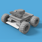
There are two versions of 37Dx geared motors — with and without encoders
For the motor control we will use Arduino board. Uno, Leonardo or any other board will be also fine.
To convert controller signals into motor power we will use a cheap L298n motor driver.
The motor has a quadrature encoder. The encoder consists of magnetic disc and a Hall sensor.

Gearbox is mounted on 3 screws
Inside there are real metal gears — no plastic at all
Beware of using long screws for mounting the motor! There is no any gear protection in the mentioned holes. Safe depth is about 4–5 mm

While the assembly check the flanges — there is only one position when you be able to put the screws.
Test bench wiring
L298N driver needs 6–12V for powering the motors. In our case it will be 12V.
Driver’s signal input bus is connected to the PWM outputs of the Arduino board

L298N driver can control two motors, but we will use only one. For the “closed-loop” control we need a feedback from the motor. In our case it is quadrature encoder pulses. For concentration only on the case and easier development we will use Arduino libraries, which are easy to install using Library Manager

- L298N library, created by Andrea Lombardo.
- Encoder library, created by Paul Stoffregen. It makes quadrature encoders reading process very easy.
- FastPid library by Mike Matera. It is an implementation of the popular PID closed-loop controller.
Encoder and FastPID we will use in the next part.
Let’s create a simple sketch which will read the numeric value from a serial port, and set PWM duty value for L298n driver:
First we need to include the L298N library.
Pin configuration. Pins 7(violet) and 8(green) are used for controlling the motor’s direction, pin 9(orange) is for the rotation speed.
driverPwm variable is used for storing the current PWM width value (control input).

Mentioned pins must be referenced while creating the motor() instance:
// create a motor instance
L298N motor(M_EN, M_IN1, M_IN2);
At the beginning of the loop() function there is a code responsible for writing the current PWM value and reading new value input:
unsigned long currentMillis = millis();
  if(currentMillis - previousMillis > interval){
    Serial.print("PWM value: ");
    Serial.println(driverPwm);
    previousMillis = currentMillis;
  }// check if data has been sent from the computer:
  // to make this code work properly, select "No line ending" in monitor
  if (Serial.available()) {
    // Narrowing convertion without check! Don't do this in production:)
    driverPwm = Serial.parseInt();
  }
The last two lines are responsible for setting the Speed (PWM width value, at this point), and setting the direction of rotation:
motor.setSpeed(driverPwm); // set motor rotation speed
motor.forward(); // set rotation direction
Attach the Arduino board and upload our sketch.
By sending values between 0–255 you can control the PWM pulse’s width:

As a bonus, let’s check the current consumed by the motor.
Maximum current, provided by the AC adapter is 5A.
Without load motor consumes about 0.2A:

Under load maximum current I get is ~2.7A

To be continued…
In the next part we will try to read the encoder data and use it for the closed-loop PID controller. Stay tuned!